3D Scanning

Reverse Engineering

3D-Scans for Reverse Engineering

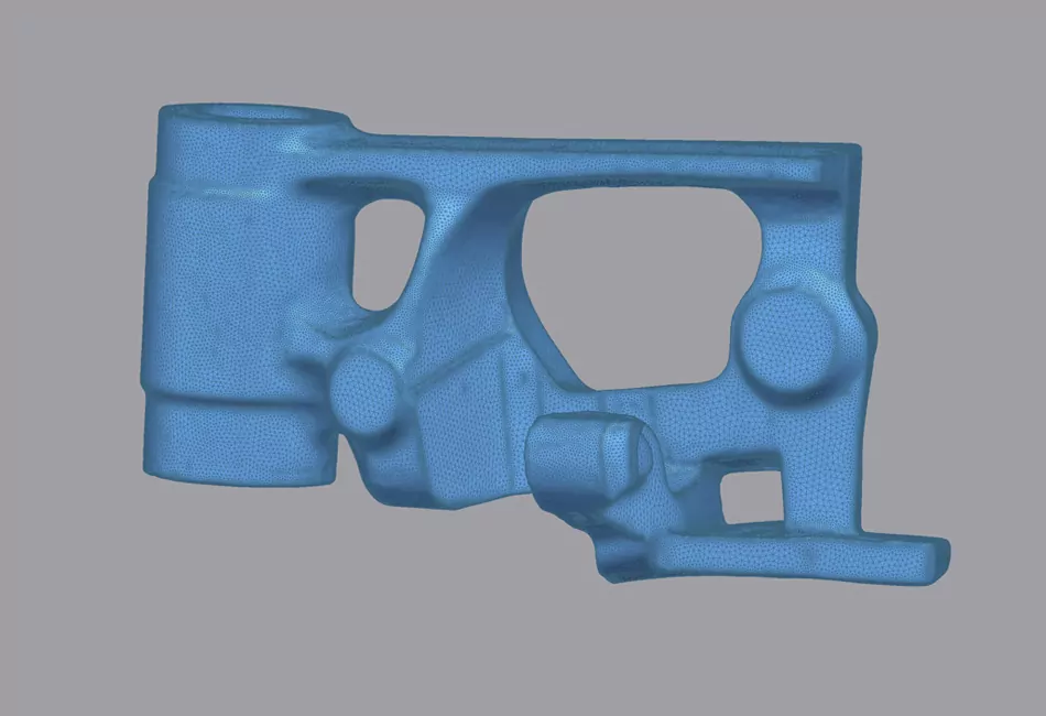
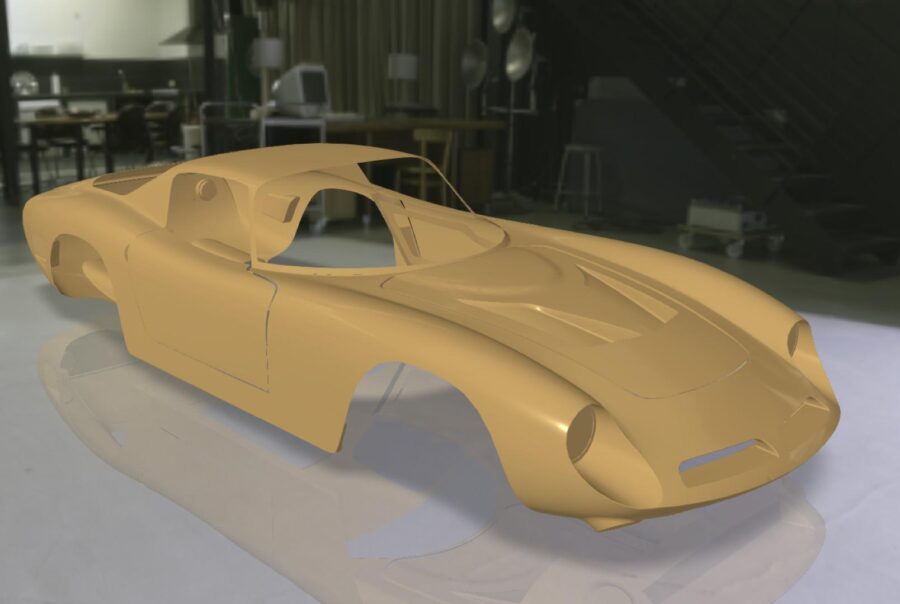
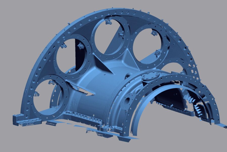
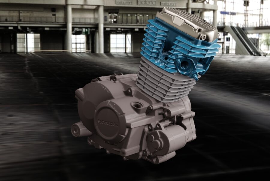
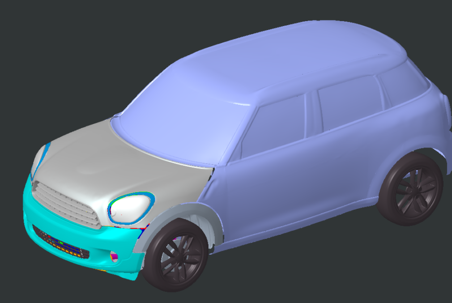
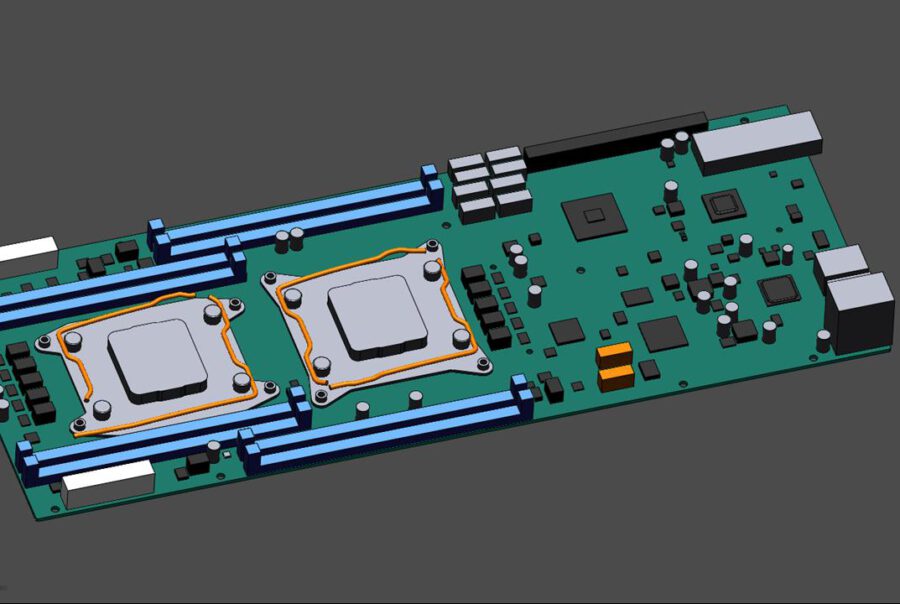
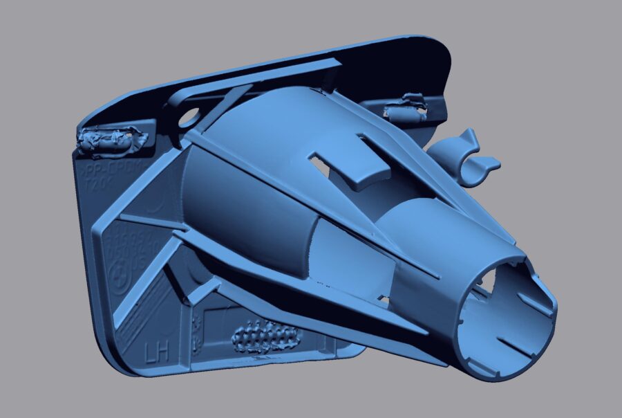
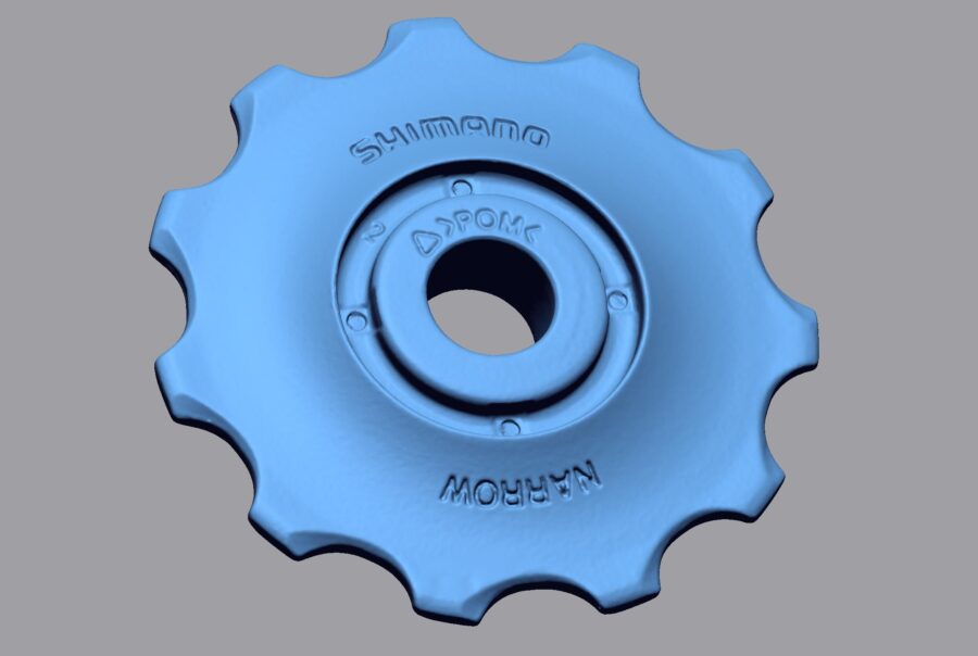
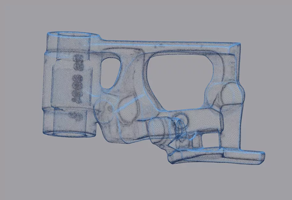
Surface reconstruction is part of the reverse engineering process, in which existing objects or components are understood and digitally reconstructed through analysis and reproduction. In recent years, 3D scanning has become an indispensable tool for this demanding task.

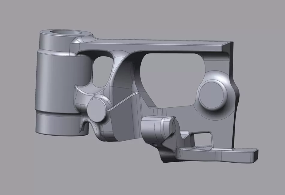
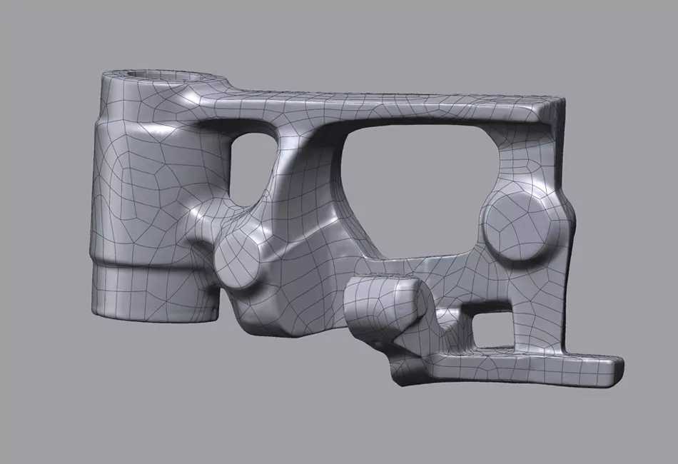
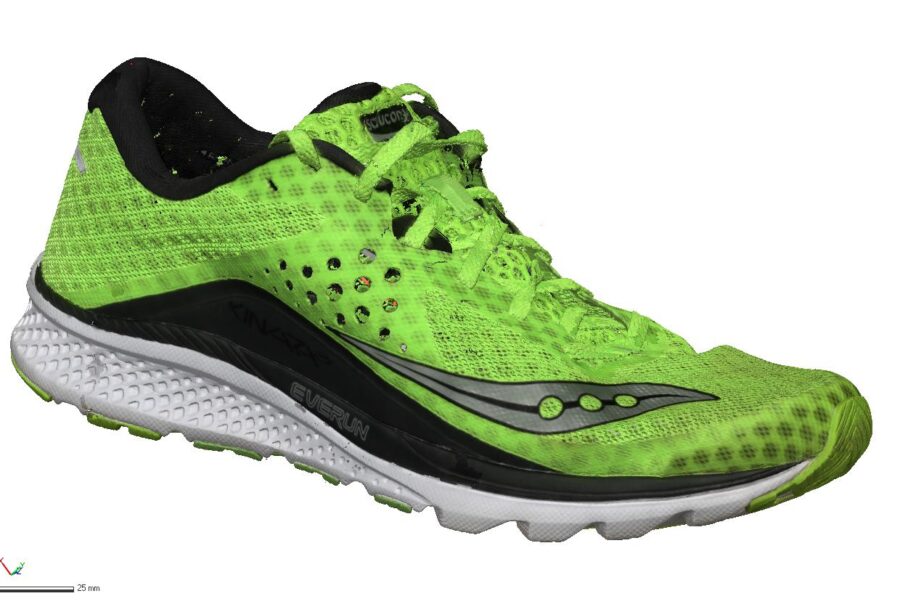
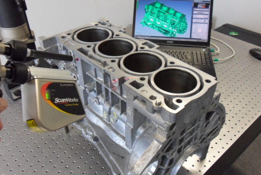
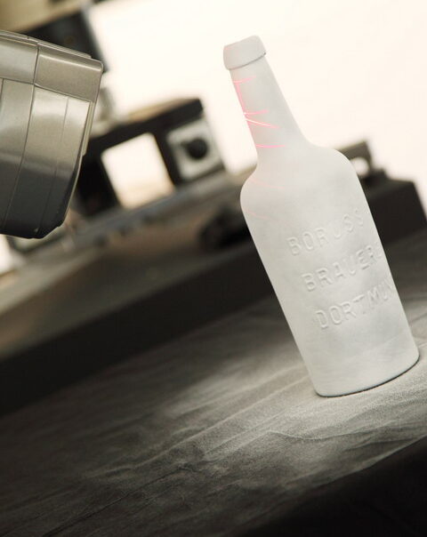
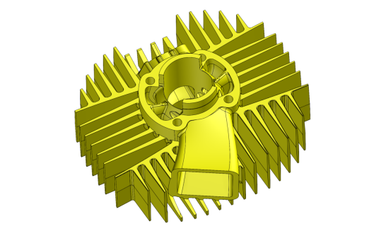
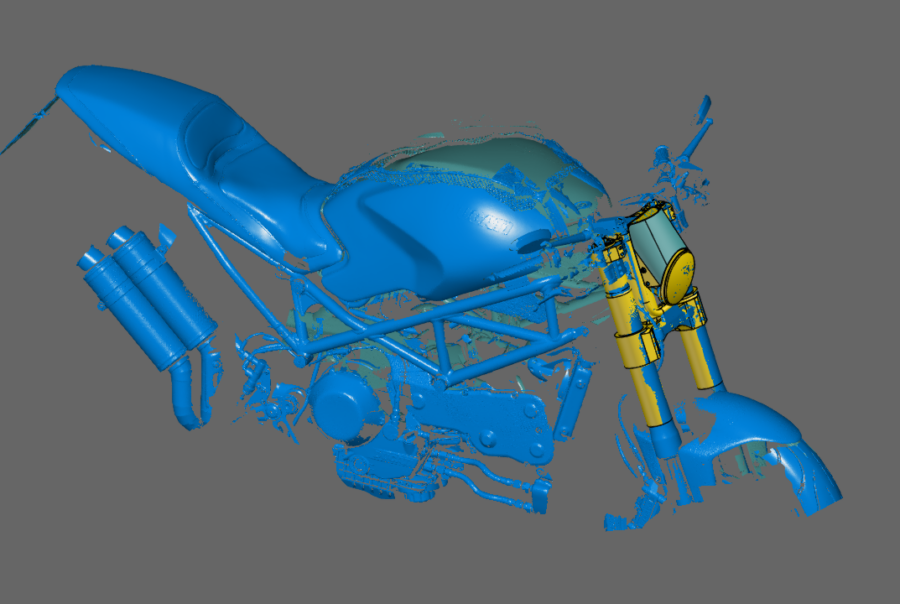
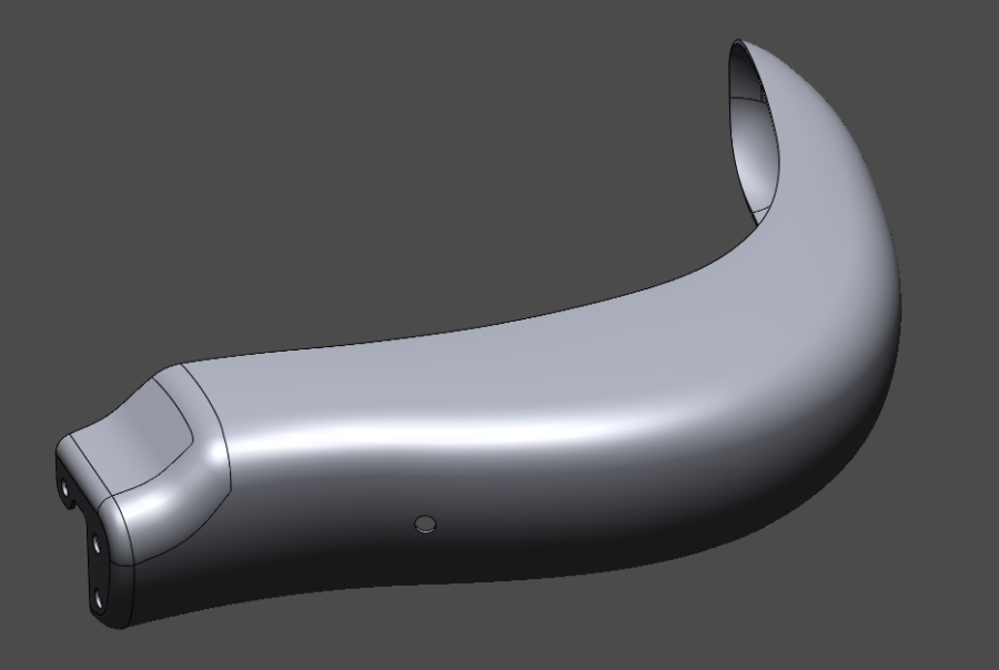
For 3D close-range scanning, we use mobile 3D scanners, the T-Scan LV laser scanner from Zeiss (Steinbichler) or the Comet L3D stripe projection scanner from Zeiss (Steinbichler). With these 3D scanners, we can digitize components of almost all sizes. The accuracy of the scanners is between approx. 6 µm and approx. 200 µm, depending on the measurement volume. The scanners work without contact and can usually scan almost all surfaces without object markers. We prepare the scanned point cloud of the object to be digitized using the Geomagic Design X (Rapidform XOR) software to create a CAD model. CAD models are created either through exact surface reconstruction or through parametric reconstruction of the model using a 3D CAD system. Both fall under the term reverse engineering. The 3D CAD systems we use are Creo (Pro/Engineer) and Autodesk Inventor.
3D Scans, what it's for

Precise capture of physical objects

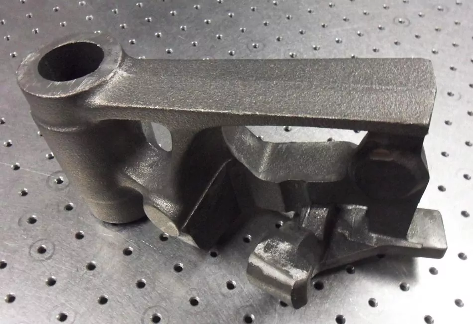
With the help of a 3D scanner and its 3D scans, physical objects can be captured extremely precisely. These scanners not only capture the external shape of an object, but also its internal structure and surface texture. This makes it possible to convert even the most complex parts into digital 3D models that can be processed on the computer. Various scanning technologies are used, such as laser scanners, structured light scanners, computer tomography and photogrammetric systems.

Reverse Engineering and 3D-Scans

Analyzing and reconstructing products

Once in digital form, these 3D models can then be used for reverse engineering. This means that engineers can analyze the design and functionality of an existing product without having the original plans or CAD files. This is particularly useful when there is no documentation for older products or when modifications or improvements need to be made.

Applications in various industries

Innovation and Efficiency

In many industries, from aerospace to automotive, the use of 3D scanning for reverse engineering has led to innovation and increased efficiency. Companies can optimize existing products or produce replacement parts without having to make expensive tooling changes. 3D scanning technology has made reverse engineering a powerful tool for product development and improvement.

For close-range 3D scanning we use mobile 3D scanners, laser scanners or stripe projection scanners, as well as photogrammetry systems.

Workflow: Reverse engineering

Various methods of Reverse Engineering

There are different variations of the reverse engineering process that are used depending on the specific requirements and the type of object. Here are some common variations:

Difference between surface model and volume model

Surface models and solid models are two different ways of representing 3D objects in computer graphics and CAD design. Here are the main differences between surface models and solid models:

Surface models:

1. Surface representation

Surface models are models that represent only the outer surface of an object. This surface is represented by a collection of connected surfaces (e.g. triangles or polygons, freeform surfaces or regular geometry).

2. Lower storage requirements

Surface models tend to have lower memory requirements than solid models because they only store the outer boundaries of an object.

3. For visual representations

Surface models are well suited for visual representations and animations because they can accurately represent the external shape of an object. They are often used in the entertainment industry, game development, and architectural visualization.

4. Incomplete information

Because surface models only represent the external surface, they often lack the internal structure of an object such as holes, channels or undercuts. This means that they are not always suitable for representing information about cavities or internal components.

Volume models:

1. Volume representation

Solid models represent the entirety of an object, including its external surface and its internal space. They consist of regular geometries or freeform surfaces that describe the entire space inside and outside the object.

2. Larger storage requirements

Solid models typically require more storage space than surface models because they store information about the entire space, even within an object.

3. For analysis and simulation

Solid models are well suited for engineering analysis, simulation and calculations because they can accurately represent the internal structure of an object. They are often used in medical imaging, finite element analysis or fluid dynamics analysis and materials science. They are mandatory in CNC manufacturing or additive manufacturing (3D printing).

4. Comprehensive information

Solid models provide more comprehensive information about the internal structure of objects, making them indispensable for scientific and engineering applications.

In many cases, the choice between surface and solid models depends on the specific needs of a project. When it comes to visually representing the external shape of an object, surface models are often sufficient. However, when detailed analysis, simulation, manufacturing processes or representation of the internal structure are required, solid models are the better choice.

process of surface reconstruction using 3D scanning

Surface reconstruction using 3D scanning is a crucial process in the field of reverse engineering and digital manufacturing. This process focuses on capturing and converting the surfaces of geometric objects into digital models that can be used in various applications such as 3D printing, CAD modeling, and quality control. The process of reverse engineering using 3D scanning is explained in more detail below.

Advantages of Reverse Engineering

Reverse engineering is an essential technique to accurately maintain the original design intent when converting physical objects into digital models.

Here are some of the main advantages of these procedures:

1. Digitization of physical objects

Reverse engineering enables precise digitization of physical objects. This is especially useful when you need to convert real-world objects into digital models, be it for design, analysis, archiving, scaling, or manufacturing purposes.

2. Reverse Engineering

Reverse engineering is a key process in reverse engineering. It enables existing products or components to be analyzed, reconstructed, scaled and improved without relying on original design data or drawings.

3. Precise detection of surfaces

These methods offer the possibility of capturing the surfaces of objects with extreme precision. This is particularly important in areas such as medicine, aerospace, architecture and the automotive industry.

4. Quality control

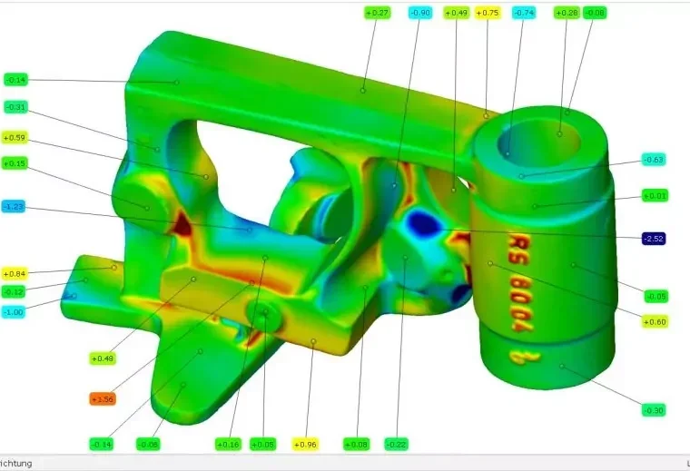
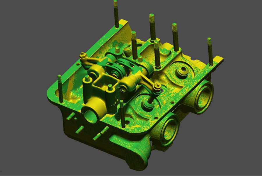
Reverse engineering is used very effectively in quality control to ensure that manufactured parts or products meet the original design requirements. Geometric deviations can be quickly identified and corrected by overlaying the digital CAD model (the target) with the 3D scan data (the actual).

5. Efficient modeling

In computer graphics and design, reverse engineering techniques enable the fast and efficient creation of 3D models. This is particularly important for animation projects, computer games and architectural visualizations.

6. Medical Applications

In medicine, reverse engineering techniques are often used to create patient-specific models, implants and prostheses. They are also crucial in surgical planning and simulation.

7. Reduced development costs & data volume

By using existing physical prototypes or models and converting them into digital formats, development costs can be reduced. This saves time and resources. Reverse engineering significantly reduces the amount of data.

8. 3D-Druck & Fertigung

Reverse engineering makes it possible to create 3D models for 3D printing or CNC machining. This is crucial for producing prototypes, custom-made parts and even for the production of art objects.

9. Construction and Architecture

In architecture, reverse engineering enables the creation of digital models of buildings, monuments and historical sites. This can be useful in renovation, restoration and planning of construction projects.

10. Research & Scientific Analysis

Reverse engineering techniques are also of great importance in scientific research and analysis. They can be used in the study of material structures, biological tissues, geological formations and much more.

Ready to collaborate?

Differences Between CAD and CNC

CNC (Computerized Numerical Control) and CAD (Computer-Aided Design) are two different but closely related technologies used in the manufacturing industry and design process. Here are the main differences between CNC and CAD:

Need to „CAD“ (Computer-Aided Design):

1. Function

CAD software is used to create 2D and 3D models of products, components or buildings. It is a design and drawing tool that allows engineers and designers to create, modify and analyze digital CAD models. This CAD model serves as a virtual representation of real objects and enables precise design and verification before actual manufacture or implementation.

2. Areas of application

CAD is used in a variety of industries, including engineering, architecture, electronics design, automotive, and aerospace. It is used to design and visualize products and buildings before they are built or manufactured.

3. Creation of drafts

CAD allows users to create precise 3D models and derive technical drawings from them that contain all relevant dimensions and details. These drawings serve as the basis for the design process.

4. Creative Process

CAD supports the creative process of design and provides tools for creating and manipulating shapes, surfaces and structures. It also facilitates the creation of prototypes and CAE simulations, such as FEM analyses or flow analyses.

5. Output

The output of CAD software is digital 2D and 3D models, technical drawings and files that can be used to communicate with other teams or to create physical prototypes.

CNC (Computerized Numerical Control):

1. Function

CNC is an automated manufacturing technology that uses computer-controlled machines to create physical objects based on digital designs (CAD files). CNC machines are capable of precise and repeatable machining and manufacturing processes.

2. Areas of application

CNC is used in the manufacturing industry to machine a variety of materials such as metal, wood, plastic and more. This includes milling, turning, drilling, cutting and 3D printing.

3. Creation of drafts

CNC machines read digital CAD files that contain the design of a part or product. Based on this CAD data, they control the tools and movements to create the physical object.

4. Creative Process

CNC offers high precision and reproducibility in the manufacture of parts. It minimizes human errors and enables the production of complex components with tight tolerances.

5. Output

The output of CNC is physical parts or workpieces that exactly match the specifications in the CAD file. CNC is often used in mass production to produce components in large quantities.

Optimal CNC data is reconstructed from the component using 3D scanning

The use of 3D scans to reconstruct optimal CNC data has revolutionized the manufacturing industry. This innovative technology represents an important step towards Industry 4.0.

Overall, CAD and CNC complement each other because CAD allows the creation of digital models that are then used by CNC machines to produce physical parts. This combination has improved and accelerated manufacturing processes in many industries.

The importance of 3D scans

Precise capture of components

The key to the success of this approach is the precise capture of components using 3D scanning. These high-resolution scanners are able to capture every detail of a component, including its complex geometry, surface finish and any defects. This enables an extremely accurate representation of the component in digital form.

reconstruction of optimal CNC data

Efficient machining thanks to precise information

The captured 3D scan data is then converted into CNC data, which forms the basis for machining. This process enables the creation of optimal CNC programs that are perfectly tailored to the component. By taking the exact shape and dimensions of the component into account, unnecessary material waste can be avoided and machining time can be significantly reduced.

The advantages of CNC

Precision, efficiency and sustainability

The reconstruction of optimal CNC data using 3D scanning offers numerous advantages. The CNC programs are extremely precise and result in components of the highest quality. At the same time, resources are saved because the optimized programs allow for less material waste and shorter processing times. This contributes to sustainability and cost efficiency.

applications in various industries

From aerospace to medical

This approach is used in a variety of industries, from aerospace to medical. In aerospace, it enables the production of lightweight yet robust components, while in medical, it enables the precise manufacture of customized implants and prostheses. Using 3D scans to reconstruct optimal CNC data shows the enormous potential of this technology for modern manufacturing.